Use the level range to absorb a defined variation
Extraction and finishing do not always deliver a perfectly even flow. A buffer provides liquid inventory while the downstream feed follows its chosen operating rate. The low and high operating levels define the volume available for that purpose.
Set that volume from the duration and size of the expected imbalance. Excess inventory also brings product residence, cleaning and changeover consequences. It cannot correct a sustained mismatch between extraction and downstream capacity.
Select the vessel arrangement for the juice character
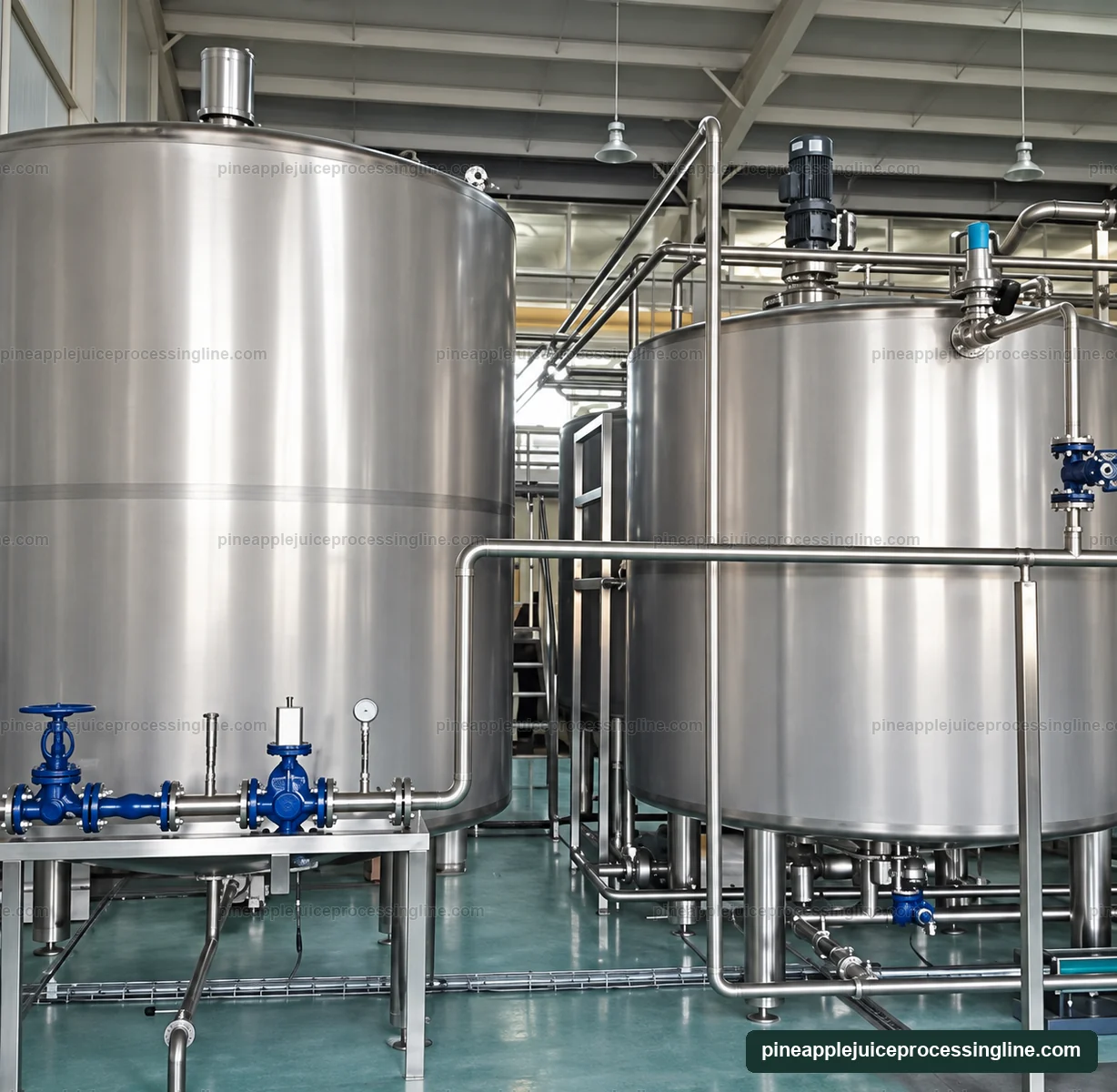
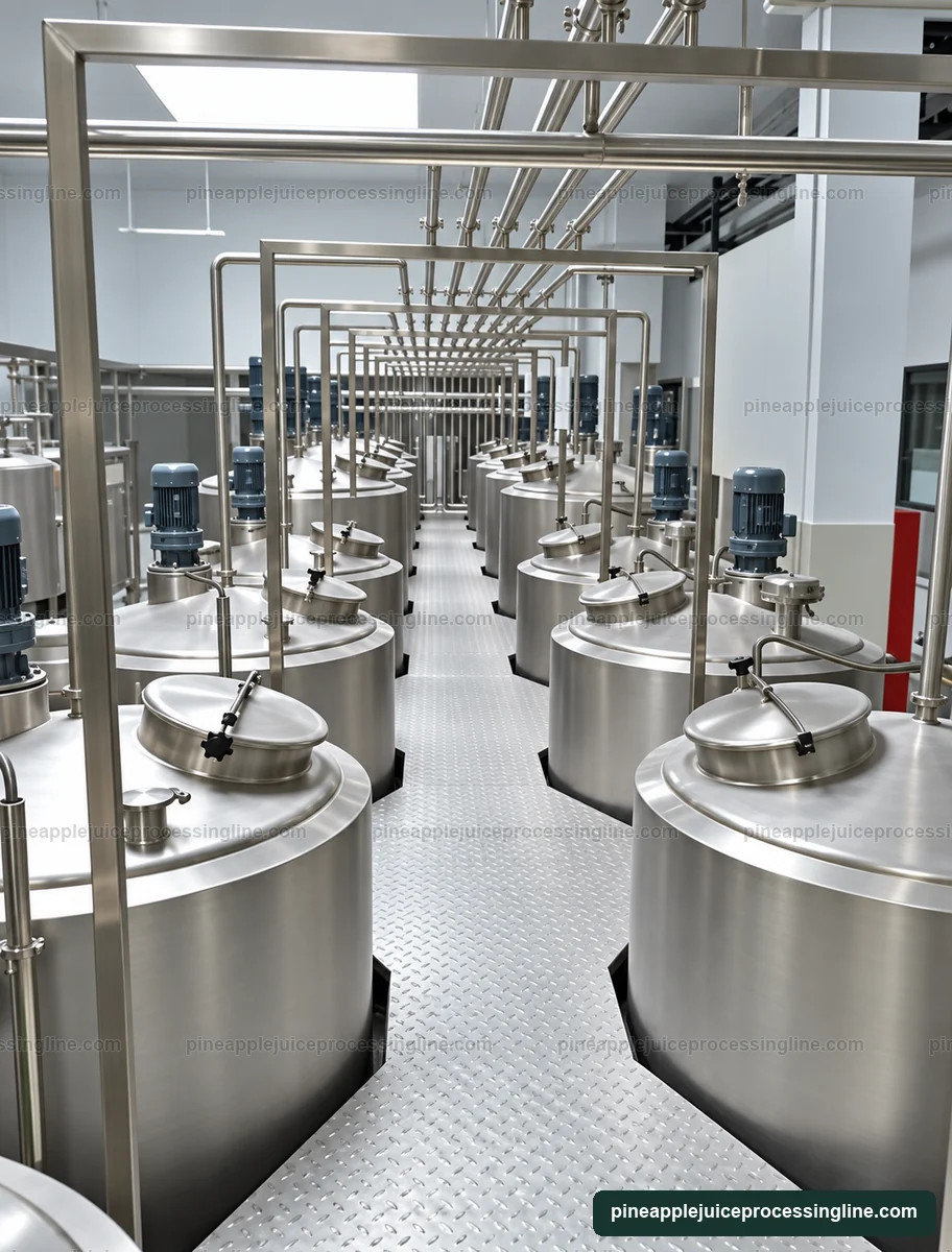
The photographed top-drive vessels illustrate an agitated configuration. Where pulp distribution must remain consistent, agitation can be evaluated alongside the outlet arrangement and permitted air entry. The chosen impeller and mixing duty follow the actual juice properties.
Clarified juice and pulp-containing juice can place different demands on holding and transfer. Include the incoming condition, intended operating temperature and permitted residence in the process specification. A general buffer tank is not an aseptic storage vessel simply because it connects to a thermal line.
Match the transfer circuit to its two ends
| Input | What it determines |
|---|---|
| Juice flow and viscosity | Required transfer duty at operating temperature |
| Fibre and permitted particles | Pump passage and acceptable product handling |
| Suction arrangement | Available inlet conditions and avoidance of unnecessary air entry |
| Receiving-machine pressure | Pump and pipe pressure duty |
| Operating levels | Low-level protection and upstream/downstream interlocks |
| Cleaning route | Drainage, valve positions and return path |
Keep the tank duty separate from fruit intake
The flow after pressing and finishing depends on the prepared feed and the measured separation balance. Use that juice stream when selecting the buffer and transfer equipment. An incoming fruit figure in tonnes per hour cannot be entered directly as a tank feed in litres per hour.
Specify gross vessel volume and operating volume separately, then include the outlet, pump, bypasses and low points in the cleaning plan. Access for drain checks and instrument service should remain clear after pipe installation.
At this stage
Practical questions
Which pump type belongs after the juice buffer?
Select it from the juice properties, solids, flow, suction conditions and downstream pressure. The tank photograph or whole-fruit intake rate does not identify the pump duty.